One of Diablo’s most iconic visuals (and, by extension, many of the games that have followed in its footsteps) is the UI’s resource globes, which display the player’s current health and mana points:
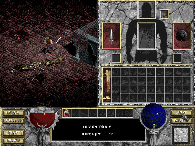
While they are technically just classic health bars, they have become a staple of the ARPG genre and exist in many variations.
So I was intrigued to create one myself, and luckily it can be done in a shader without having to create too many assets besides some generic noise/pattern textures. I’m using Unreal’s material graph, but the techniques are the same in other material-authoring sytems or when writing shaders hlsl/glsl.
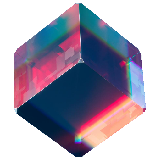
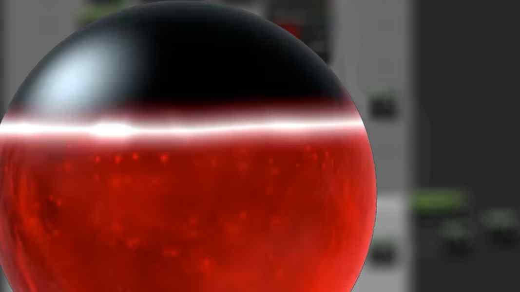
This is the final result:
It consists of several elements layered on top of each other, and below I’ll cover the creation of each element and how to combine them.
These elements are
- The fluid
- The glass sphere
- The glowing edge at the fluid level.
But before I delve into the creation of these elements, some setup is needed because both the glass and the fluid need a sphere as a base to work with.
Creating the Sphere
For both the fluid and the glass, you need the UVs, mask and normals of a sphere. You could use a texture for this, but since the sphere is such a simple geometric shape, it’s tempting to just create it in a material function using math:
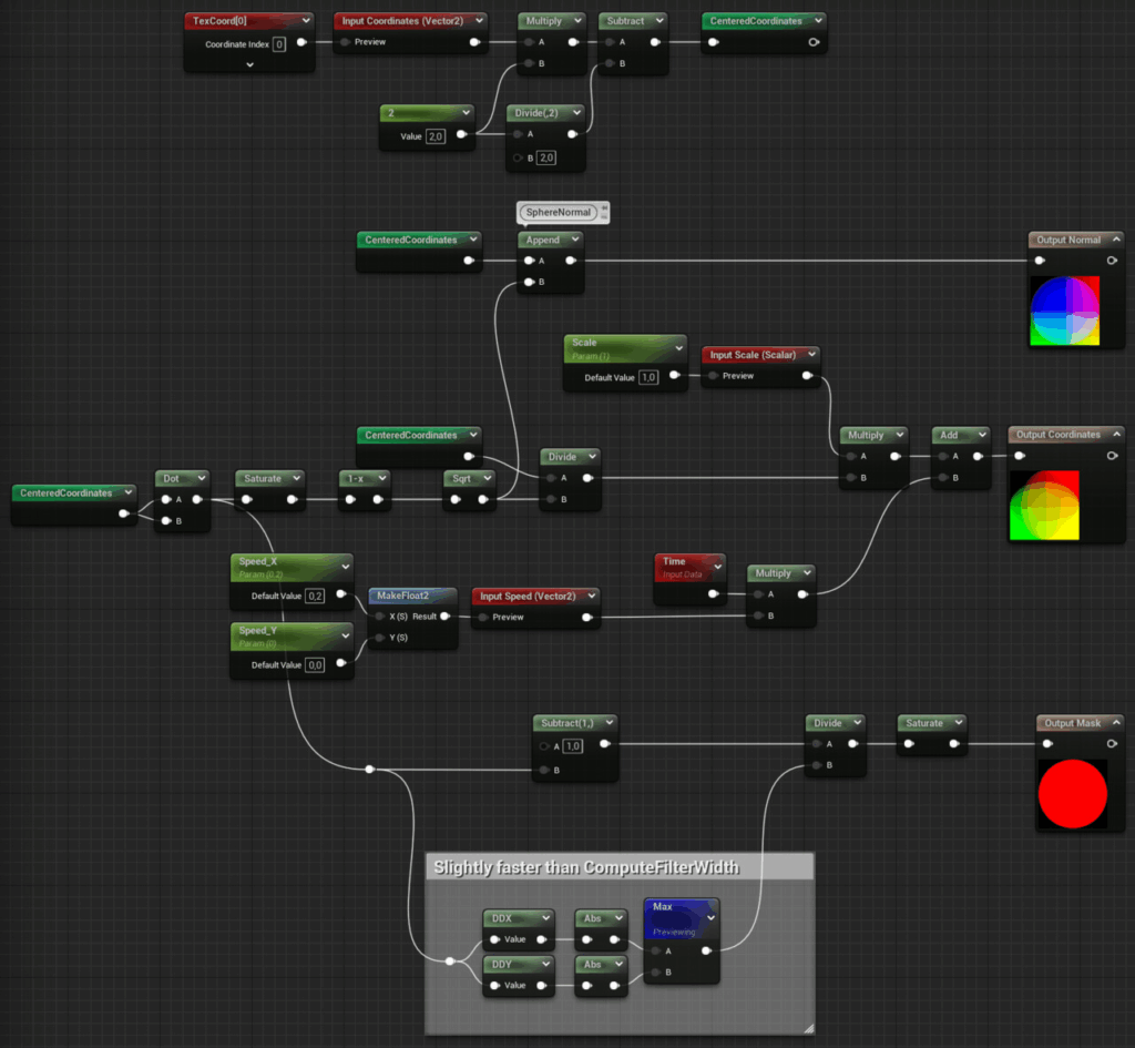
This material function is based on this code snippet by Ben Golus. It returns the normals, coordinates and a mask.
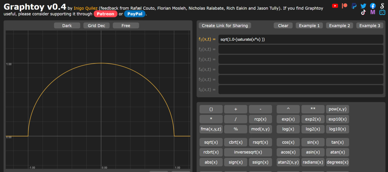
The x and y components of the normal are the centered coordinates, while the z component is the square root of the inverted and saturated dot product. This isn’t exactly intuitive, but if you type this formula into graphtoy, you can see how the resulting graph shows the height of a sphere:
To get the sphere coordinates, the centered coordinates are distorted by the sphere height, so that a texture mapped to these coordinates will appear smaller towards the edges.
The coordinates are also already panned in this function. This will be relevant later, as the fluid is supposed to move as if it’s boiling, so having a panning function already in this function will help with that.
The last of the outputs is a mask, and while it’s probably the easiest one to calculate, I want to stress the point that I’m not just using a step function or an if node to create the mask, but I’m dividing the distance to the edge of the mask by its derivative and saturating the result. This creates an anti-aliased edge with 0-1 values at the pixels directly on the edge.
Creating the Fluid
To create the fluid, I started by creating a matching texture in Substance Designer:
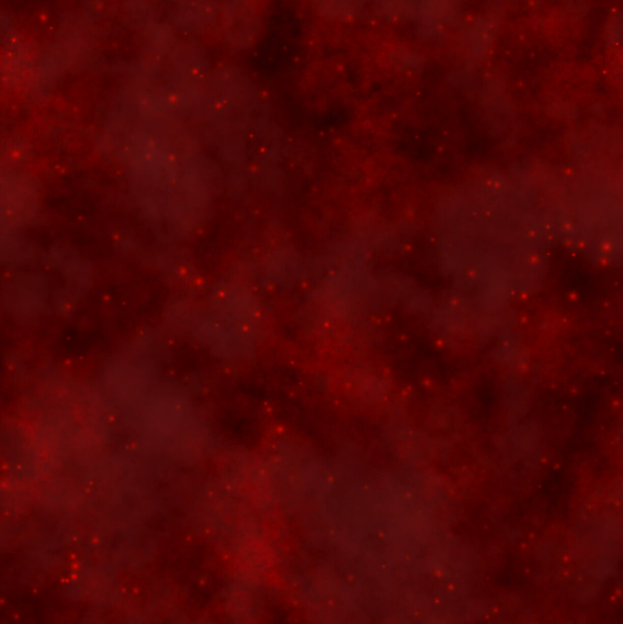
It’s basically a cloud pattern with some spots and sparkles added to it. Looking at the texture now, a grayscale version would probably have sufficed and given me the option to add the color in the shader, but my inital idea was to work with two contrasting colors, before I switched to a classic amber red.

As already mentioned, the sphere material functions have a panning feature, and I’m using it here to have two layers with slightly different speeds and scales move on top of each other. On top of that, I added a third layer that uses undistorted UVs. While the fluid near the glass is the most visible, the fluid should have some depth, and the undistorted texture represents moving particles further inside the sphere. Instead of lerping between the layers, I just added them all together and added a multiplier to control the final brightness. In the screenshot above, you can also see that I pipe the normal and mask output of the first sphere material function into named reroutes, as they are needed in the remaining elements.
Creating the Glowing Edge
Since the bubble is supposed to display critical information to the player, it makes sense to highlight the position of the current fill level by adding a noticeable glow effect to it.
Before adding the actual glow effect, there needs to be a fill level to work with. And since we want the fluid to move, we also need some waves:
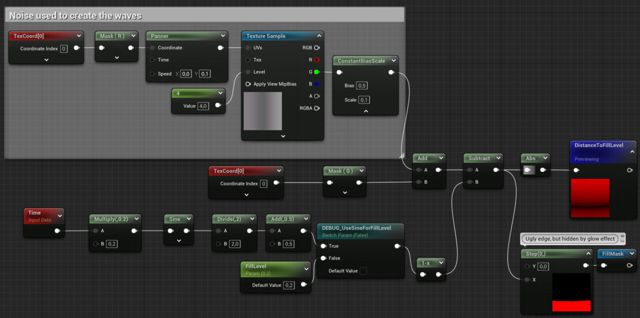
In this screenshot you can see how the waves are created. I use a panning texture, but map it to the U channel only, so Iget a gradient along the horizontal axis. This gradient is then centered around 0 and added to the V channel to create the wave effect. Then the fill level is subtracted (I had to add a 1-x node there to fix the direction). The result is the signed distance (along the vertical axis) to the fill level. The step function is used to create the fill mask. This function returns 1 for all pixels with values greater than 0 and 0 for all pixels with values less than zero. This mask will be used later for compositing. The other result of this part of the graph is the DistanceToFillLevel variable. This can be used to create the glow effect.
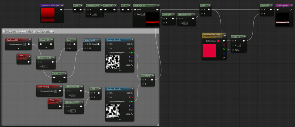
At its core, the Glow effect is just the inverted DistanceToFillLevel variable, adjusted by using a multiplicator and a power node. To add a sense of pulsating magical energy, two noise patterns panned at slightly different speeds are blended into it. To add some color, the result is then used to lerp between the actual desired color and pure white. This emulates the behavior of Unreal’s tonemapper, which desaturates pixels as they get brighter. This emulates the behavior of real-world cameras and helps convey a wider range of contrast than the display is actually capable of.
Creating the Glass
Because glass is transparent, it is primarily visible through reflections and specular highlights. So to create the glass visual, it’s enough to create the highlights.
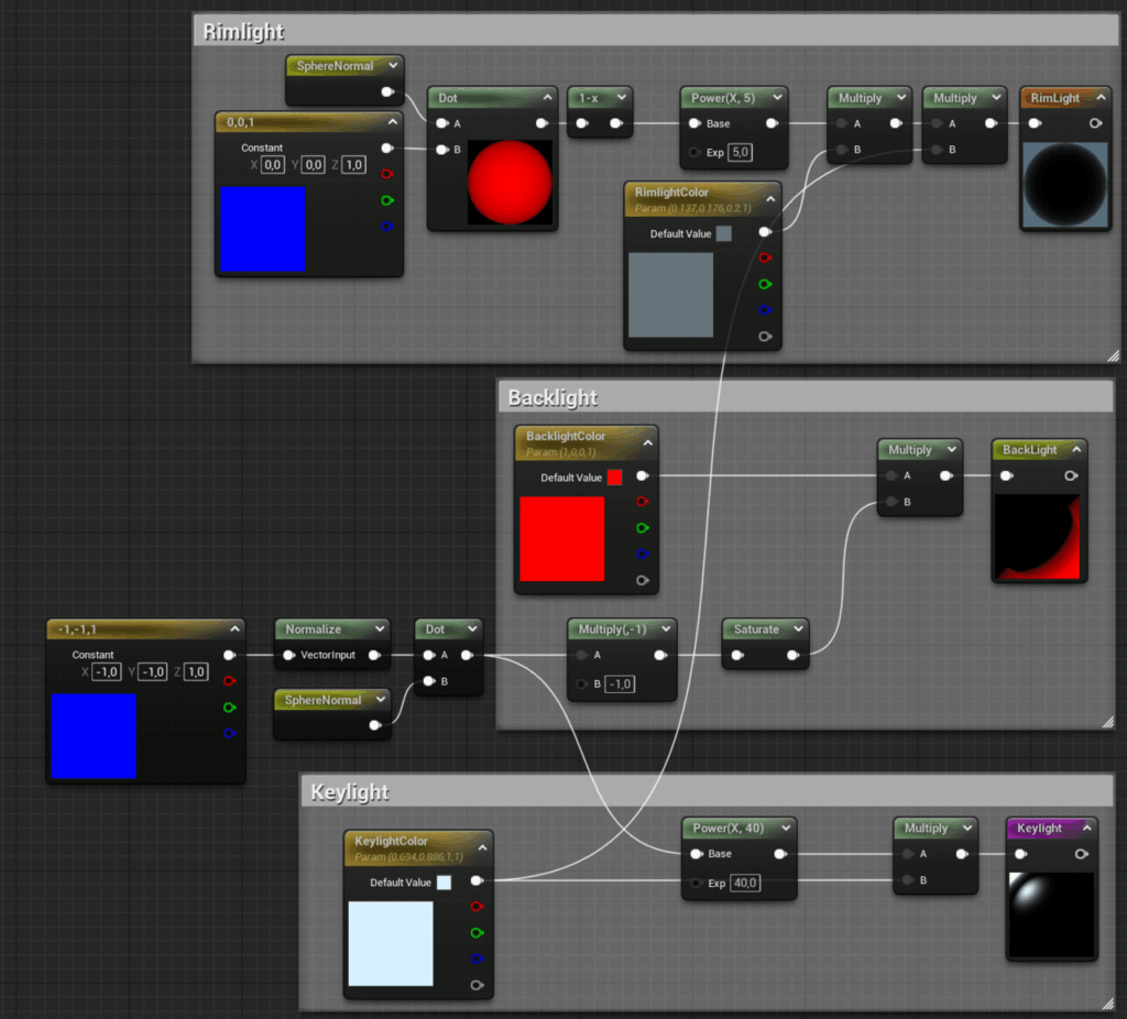
To create a highlight, all you need to do is compute the dot product of a light vector and the surface normal vector illuminated by it, use a power node to control the size (the larger the exponent, the smaller it gets), and multiply it by a color to control its color and intensity. As you can see in the screenshot above, this is how the highlight for the button light was created. For the backlight, the dot product was inverted so that it comes from the opposite direction as the key light. For the edge light, the dot product is subtracted from 1 to get a Fresnel effect.
Combining the Elements
Once all the elements are created, combining them is relatively simple:
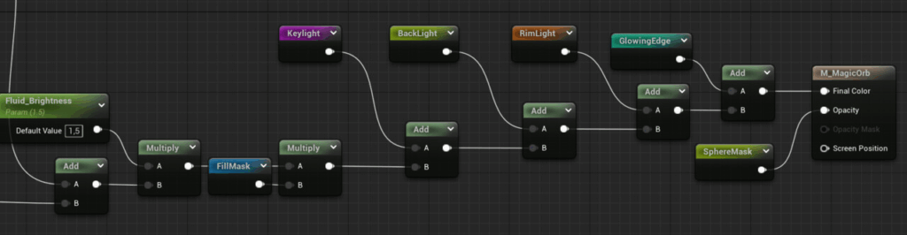
The fluid is multiplied by the fill mask, and then all the highlights and the glowing edge are added. Since all the elements except the fluid are lights, just adding them works without any further blending operations. Finally, the sphere mask is applied to the opacity.
As you may have already noticed so far, all techniques used so far are relatively simple and isolated from each other, so it’s easy to play around with the individual elements to try different looks and techniques. By adjusting the colors, used textures or just speeds and intensity parameters, you can create different versions for different kinds of resources.